


Medical device enclosure projects often run into problems before production begins.
A 3D printed prototype may fit well, but the injection-molded part may show sink marks, warpage, weld lines, gate marks, or assembly issues. A clean-looking cosmetic surface may be affected by ribs, screw bosses, snap-fits, PCB supports, or thick wall sections hidden on the inside. A customer may need real molded parts for validation, but full production tooling may be too early when volume is still uncertain. For white, light-colored, matte, or glossy medical housings, dust, fingerprints, scratches, oil marks, and packaging contamination may also become acceptance issues if cleanliness and handling requirements are not clearly defined.
This is why medical device enclosure manufacturing should not be treated as ordinary plastic part sourcing.
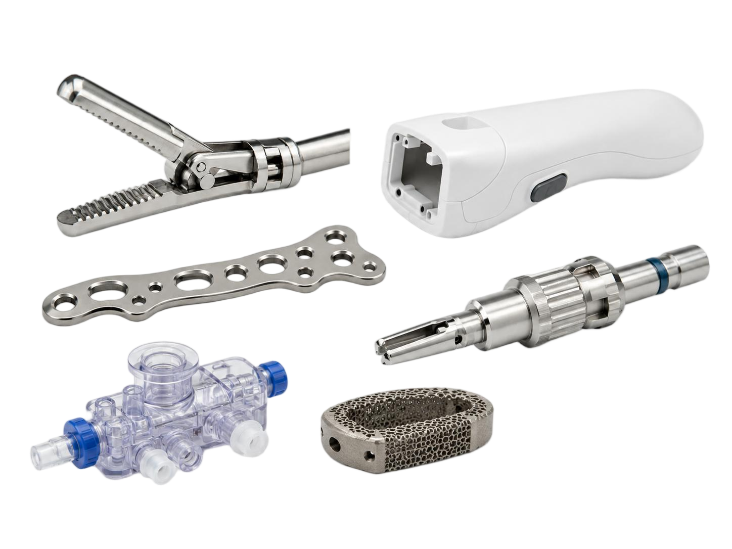
For diagnostic equipment, POCT devices, laboratory instruments, handheld medical devices, and low-volume medical products, enclosure manufacturing requires a practical engineering path:
DFM review → prototype validation → material and tooling review → rapid tooling or shared mold base tooling → trial molding → clean injection molding and controlled handling → low-volume production
Rapid MFG Online supports medical device enclosure projects by helping engineering teams identify manufacturability risks before tooling, select a suitable manufacturing route, obtain real molded parts for validation, and move from prototype to low-volume production with lower project risk.
This article focuses on external plastic enclosures and housings for medical and diagnostic equipment. Parts involving patient contact, fluid paths, biological samples, sterile packaging, implantable applications, or regulated medical performance require separate material, regulatory, and validation review.
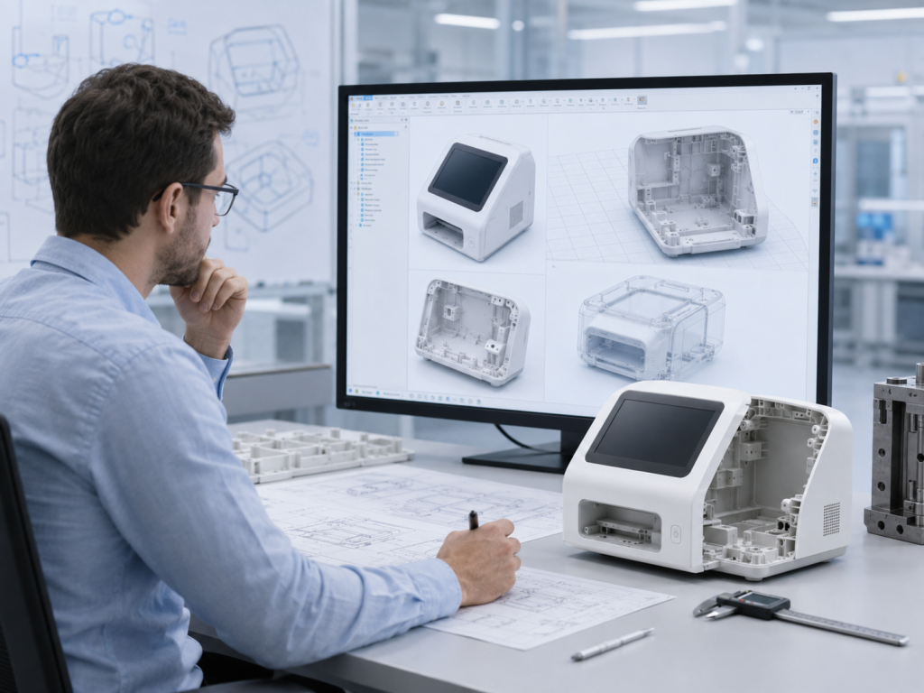
1. Start with DFM Before Tooling
For medical device enclosures, tooling should not be the first engineering step.
Before a mold is built, the part should be reviewed for injection molding, appearance, assembly, material behavior, tolerance control, and production stage. Many issues that are not visible in CNC or 3D printed prototypes can become real problems during injection molding.
A useful DFM review should not only answer whether the part can be molded. It should identify what may go wrong during molding, assembly, inspection, and low-volume production.
Key review items include:
DFM Review Item | Engineering Purpose |
Wall thickness | Identify local thick sections, sink mark risk, warpage, and cooling imbalance |
Cosmetic A-surfaces | Protect visible surfaces from gate marks, parting lines, ejector marks, and sink marks |
Screw bosses | Check whether boss roots are too thick or located behind cosmetic surfaces |
Ribs | Review rib thickness, height, location, and impact on external appearance |
Snap-fits and undercuts | Evaluate slider, lifter, demolding, and tooling complexity |
Draft angles | Reduce drag marks, ejection damage, and demolding risk |
Gate location | Review filling path, weld line location, gate mark visibility, and cosmetic impact |
Assembly space | Check clearance for PCB, displays, batteries, sensors, connectors, and cartridge interfaces |
Material selection | Review strength, toughness, shrinkage, heat resistance, chemical exposure, and appearance |
Tolerance requirements | Confirm whether critical dimensions are realistic for injection molding |
The value of DFM is practical. A small design change before tooling is usually easier, faster, and less expensive than modifying a mold after trial molding.
For medical device enclosure projects, DFM should be treated as an engineering loop. CAD review, tooling design, trial molding feedback, and customer validation should be connected rather than handled as separate steps.
2. Cosmetic Defects Often Start Inside the Part
Medical and diagnostic equipment housings often use white, light gray, matte, glossy, or textured surfaces. These finishes are sensitive to visual defects. Small sink marks, flow marks, weld lines, gloss variation, scratches, or surface deformation may affect the perceived quality of the final product.
In many cases, cosmetic defects are not caused by the surface itself. They are caused by internal structures.
Common sources include:
- screw bosses placed behind visible surfaces;
- ribs that are too thick or too high;
- PCB support columns creating local thick sections;
- snap-fit roots adding material buildup;
- uneven wall thickness around display windows or connector openings;
- large flat panels without balanced reinforcement;
- gate or weld line positions affecting visible areas.
The solution is not to remove all internal structures. The solution is to design them in a way that supports strength and assembly without creating excessive local material thickness.
For example, screw boss bases should avoid solid material accumulation. Bosses can be supported with thinner ribs instead of thick bases. Ribs should be controlled in thickness and height. Large flat panels should be reviewed together with rib layout, gate location, and cooling behavior. Visible A-surfaces should be defined before tooling, and internal supports should be checked against external appearance zones.
This is especially important for diagnostic equipment and laboratory instruments, where the enclosure often acts as both a structural housing and a user-facing cosmetic surface.
A good enclosure design is not only about making the product look clean in CAD. It must also remain clean after molding.
3. Snap-Fits Should Be Reviewed for Tooling and Reliability
Snap-fits are common in medical device enclosures. They can reduce screws, improve appearance, and simplify assembly.
However, snap-fits can also increase tooling complexity and production risk.
A snap-fit that works in a 3D printed prototype may not work reliably in injection molding. Molded parts shrink. Materials deform differently. Undercuts may require sliders or lifters. Sharp roots may create stress concentration. Tight snap-fits may break during repeated assembly.
Before tooling, each snap-fit should be reviewed for:
- undercut direction;
- need for sliders or lifters;
- root radius;
- root thickness;
- draft angle;
- material toughness;
- deflection space;
- assembly force;
- shrinkage impact on locking clearance;
- repeated assembly or service requirements.
For low-volume medical device projects, the tooling cost caused by snap-fits should be evaluated carefully. A complex snap-fit may improve appearance, but it may also add mold actions, increase tooling cost, extend lead time, and create long-term reliability concerns.
In some projects, hidden screws, locating ribs, and simplified snap-fit structures may be more practical. This type of solution may not look as elegant in the design stage, but it can reduce tooling complexity, improve production stability, and support faster validation.
The right enclosure design is not always the most visually minimal design. It is the design that balances appearance, assembly, tooling, and production risk.
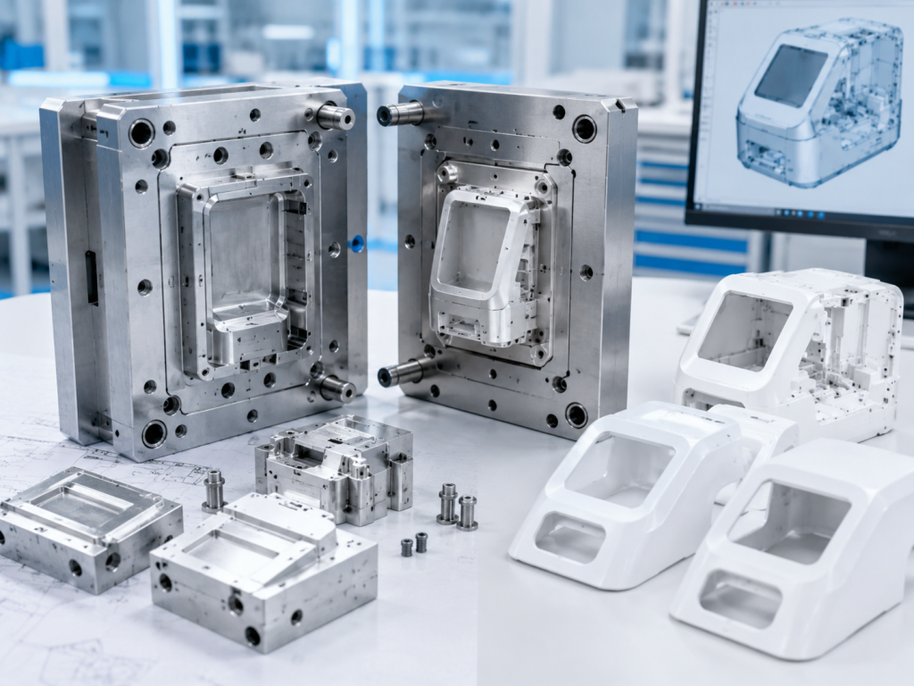
4. Prototype Validation Is Not the Same as Molded Part Validation
Most medical device enclosure projects go through prototype stages. Engineering teams may use 3D printing, CNC machining, or vacuum casting to check form, fit, appearance, and early assembly.
These processes are useful, but they cannot fully represent injection-molded parts.
3D printing is good for early form and layout validation, but printed materials, layer structure, surface quality, and mechanical behavior are different from molded parts.
CNC prototypes are useful for dimensional and functional checks, but they are cut from solid material. They do not show molding shrinkage, gate marks, weld lines, cooling behavior, or molded part warpage.
Vacuum casting can support small prototype batches and early appearance evaluation, but it should not be treated as equivalent to injection molding.
This creates a common situation:
The prototype assembles well, but the molded part has problems.
That does not mean prototypes are not valuable. It means the validation method must match the manufacturing objective.
A practical development route is:
- Use 3D printing or CNC machining to validate form, space, and early assembly.
- Conduct DFM review before injection tooling.
- Use rapid tooling when real molded parts are required.
- Validate shrinkage, warpage, cosmetic quality, assembly fit, and critical dimensions through trial molding.
- Move into low-volume production after molded part validation.
Rapid tooling is useful because it allows engineering teams to test real injection-molded parts before committing to full production tooling.
5. Tooling Strategy Matters in Low-Volume Medical Device Projects
Many medical device enclosure projects have uncertain early-stage demand.
A customer may need 20–50 prototype units, 100–300 engineering validation units, 500–1,000 pilot production units, or 2,000–5,000 initial market units before future demand becomes clear. That future demand may depend on regulatory progress, customer approval, clinical workflow validation, distributor feedback, or market response.
At this stage, full production tooling may be too early. Staying with 3D printing or CNC machining for too long may also be impractical because the customer still needs molded parts to validate real production behavior.
The better question is not:
Should we make a mold?
The better question is:
What level of tooling investment fits the current project stage?
A professional tooling decision should consider:
- current project stage;
- required quantity;
- part size and complexity;
- cosmetic requirements;
- need for molded part validation;
- future production demand;
- tooling budget;
- lead time target;
- tolerance requirements;
- expected mold life;
- possibility of later scale-up.
For medical device enclosure projects, a good quotation should not only include price and lead time. It should reflect tooling risk, molding risk, cosmetic risk, assembly risk, and the project’s production stage.
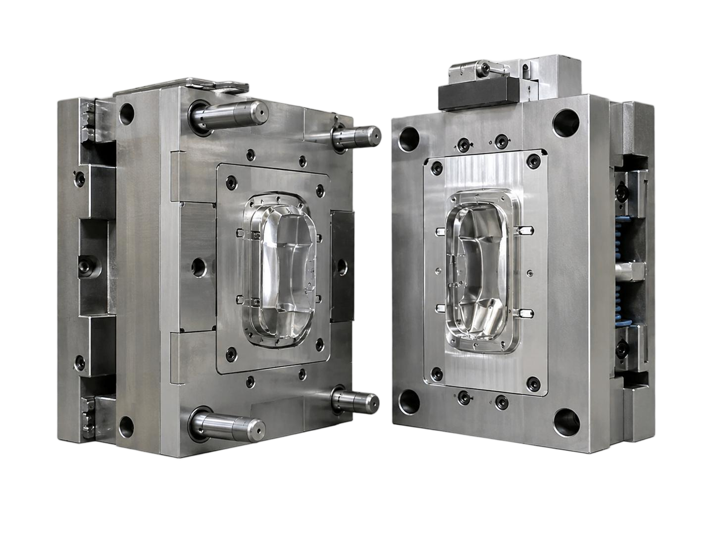
6. Shared Mold Base Rapid Tooling for Faster Validation
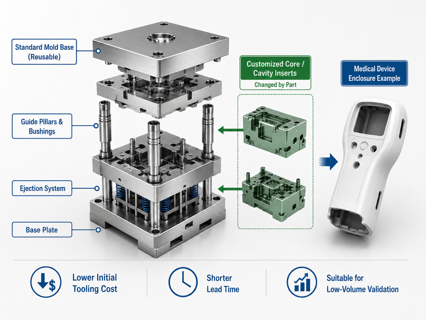
Rapid MFG Online supports rapid tooling based on shared mold base or insert-based tooling solutions.
A full dedicated injection mold usually requires a complete mold base, plates, core, cavity, cooling system, ejection system, and related mold structures. For validation-stage or low-volume projects, this level of investment may be too early.
A shared mold base solution uses a standard mold base that can be reused. The project mainly needs to manufacture the core, cavity, or inserts that define the part geometry.
This approach can provide several practical advantages:
Advantage | Practical Meaning |
Shorter tooling lead time | Less mold structure needs to be built from zero |
Lower early tooling investment | Cost is focused on the part-specific core, cavity, or inserts |
Faster molded part validation | Customers can test real injection-molded parts earlier |
Better fit for uncertain demand | Avoids premature full production tooling investment |
More practical iteration | Insert modification can be easier than rebuilding a full mold |
For simple and suitable parts, shared mold base rapid tooling can significantly shorten tooling lead time. In selected cases, core and cavity insert machining may be completed within 3–5 working days. Total project lead time still depends on part complexity, DFM confirmation, mold structure, surface requirements, trial molding, and customer approval.
For suitable parts, this approach can also reduce early tooling investment. In some cases, tooling cost may be close to one-third of a dedicated mold base solution, depending on part size, mold complexity, surface requirements, material, and expected mold life.
Shared mold base rapid tooling is especially useful for diagnostic device enclosures, POCT device housings, medical instrument enclosures, handheld medical device housings, low-volume pilot production, design validation before production tooling, and plastic enclosure projects with uncertain annual demand.
This solution is not a replacement for production tooling in every situation.
It is most suitable when the part size fits available shared mold base ranges, the enclosure is not extremely complex, real molded parts are needed quickly, and the project is still in validation, pilot production, or low-volume introduction.
It should be evaluated carefully when the part is too large, undercuts are complex, cosmetic requirements leave little tolerance for gate marks or parting lines, the mold requires complex cooling, annual volume is already high, or the customer clearly requires a full production mold.
The value of shared mold base rapid tooling is not simply lower cost. Its value is helping the customer obtain real molded parts at the right stage without over-investing too early.
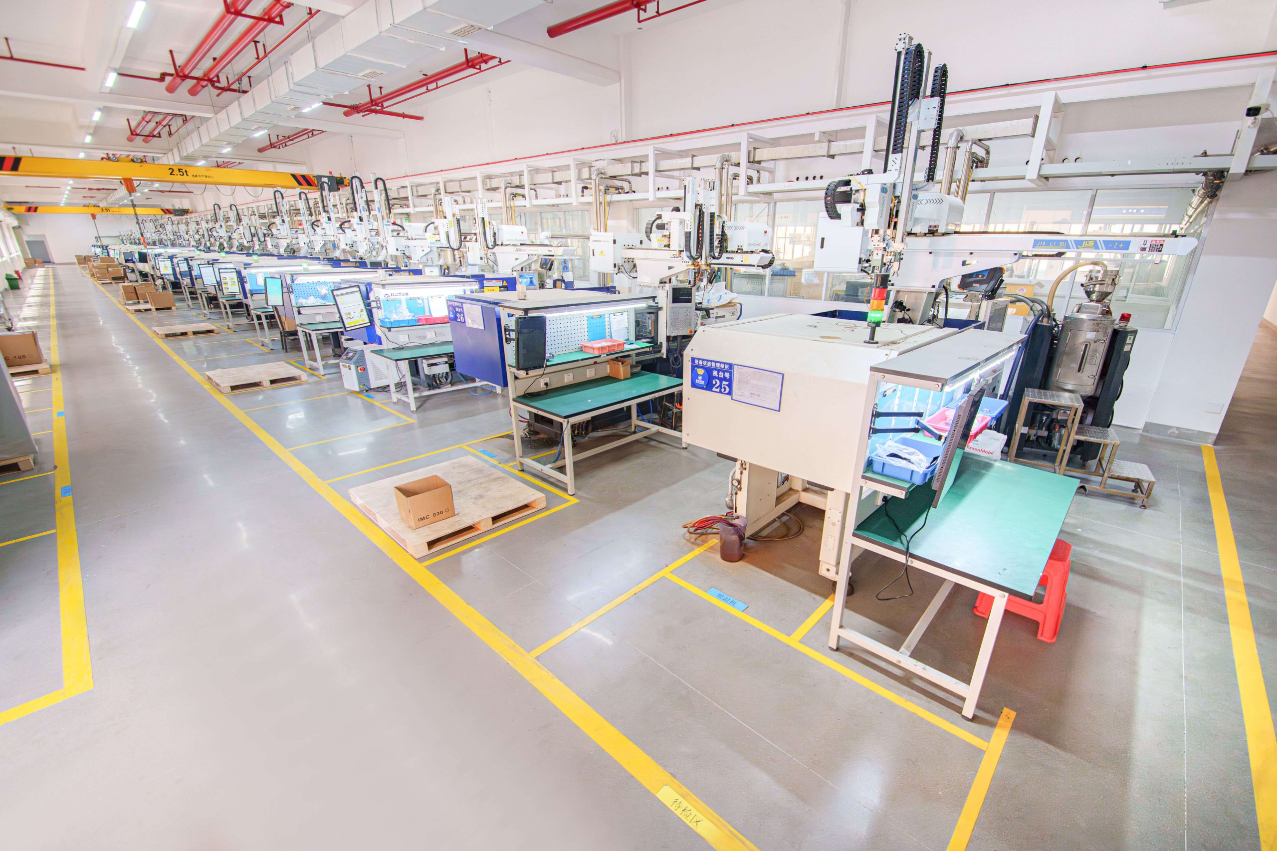
7. Clean Injection Molding and Controlled Handling
Medical and diagnostic equipment customers often ask for “clean” parts. In manufacturing, however, cleanliness can mean different things.
It may refer to no visible dust, no oil contamination, no fingerprints, controlled handling, better cosmetic consistency, cleaner molding conditions, defined cleanroom class, sterile production, or sterile packaging.
These requirements should not be mixed together.
For many medical device enclosures, diagnostic equipment housings, and laboratory instrument housings, the real requirement is not sterile manufacturing. The more common requirement is better control of dust, oil, fingerprints, scratches, handling marks, and packaging contamination.
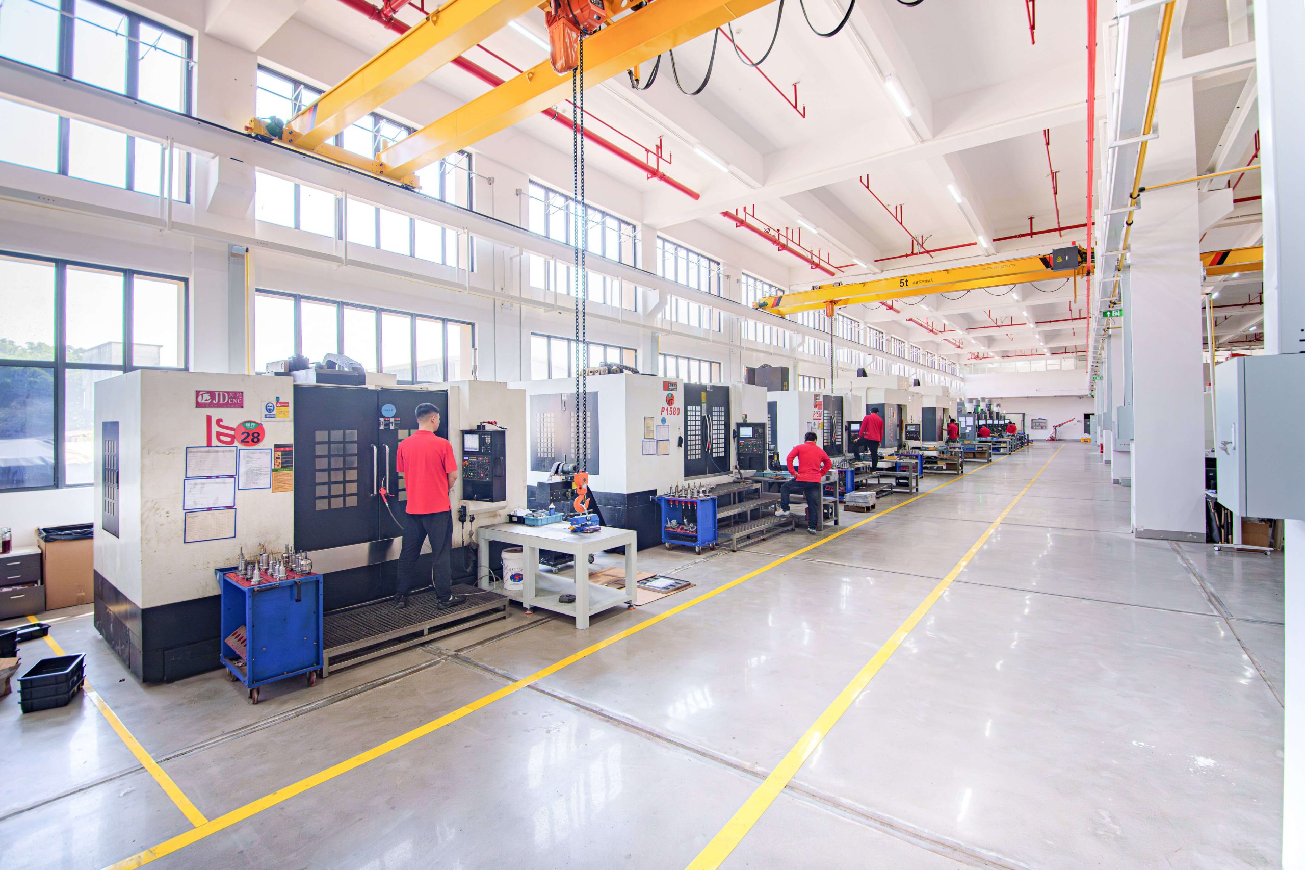
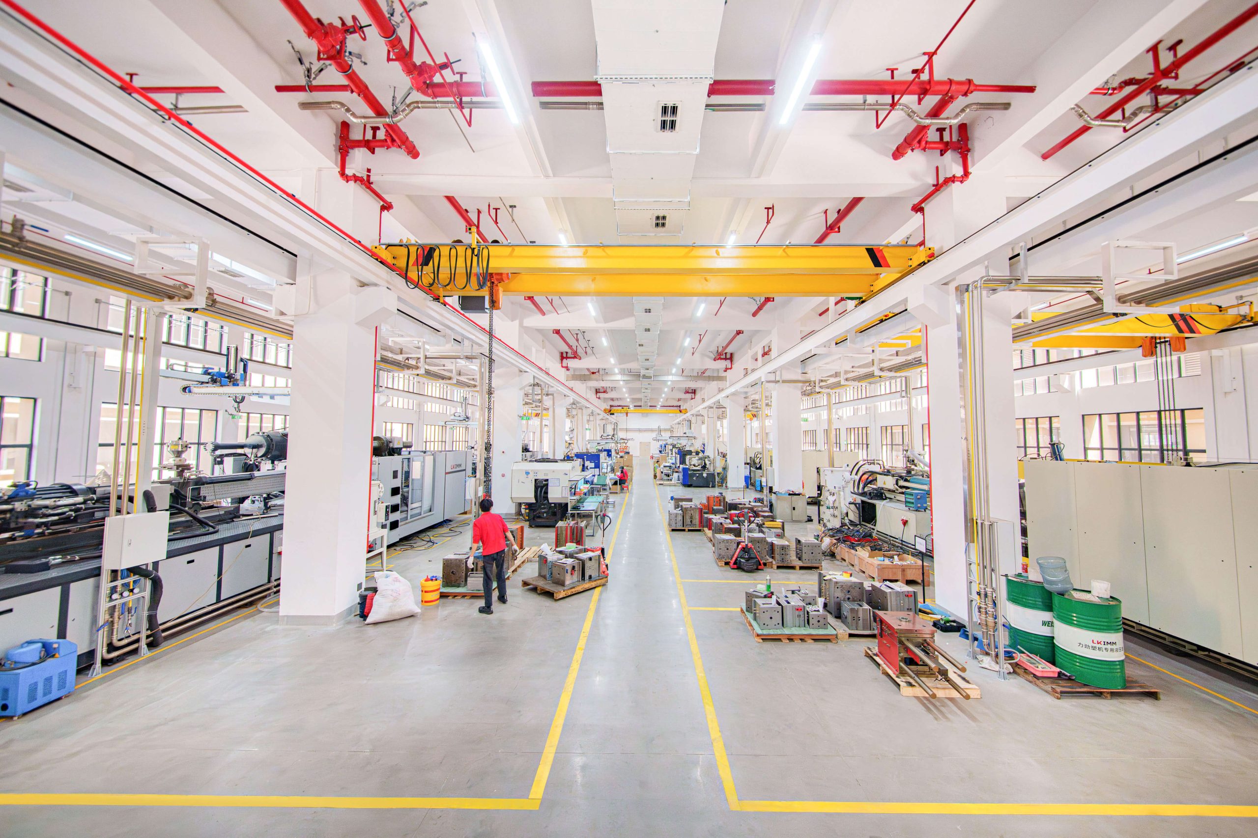
Rapid MFG Online has high-cleanliness injection molding workshop capability. The practical value is process control, not simply a cleaner room.
A cleaner and more controlled molding and handling environment helps reduce risks such as:
- dust contamination on light-colored cosmetic surfaces;
- fingerprints and oil marks on glossy or matte surfaces;
- scratches during handling;
- contamination before packaging;
- inconsistent cosmetic appearance between batches;
- surface marks during production flow.
This capability is especially useful for white or light-colored medical device enclosures, matte plastic housings, diagnostic device covers, POCT device housings, laboratory instrument housings, precision plastic parts with visible A-surfaces, and projects with defined cosmetic inspection standards.
Important clarification: unless a specific ISO cleanroom class is confirmed for the project, this capability should be understood as a cleaner and more controlled molding and handling environment, not sterile manufacturing.
High-cleanliness molding support does not replace biocompatibility review, sterile packaging validation, medical-grade validation, or customer-required cleanroom certification. If the project involves patient contact, biological samples, fluid paths, sterile packaging, or regulated medical performance, those requirements must be reviewed separately.
For many medical and diagnostic equipment enclosure projects, the practical value of cleaner molding and handling is better control of appearance, packaging, and production consistency.
8. Turning Cleanliness into an Executable Standard
Cleanliness and cosmetic quality should not remain subjective.
If the customer says “clean parts” but does not define inspection criteria, handling requirements, packaging method, or acceptance limits, quality disputes may occur later.
Before production, the following items should be clarified:
Control Item | Practical Definition |
Cosmetic surface zones | Define A, B, and C surfaces |
Visual inspection conditions | Inspection distance, lighting, angle, and viewing time |
Defect criteria | Acceptable limits for dust, scratches, black spots, color variation, sink marks, and stains |
Handling method | Gloves, trays, separators, or protective film where needed |
Packaging method | Individual bags, protective film, trays, or separated packaging |
Cleaning requirement | Wiping, dust removal, or anti-static handling if needed |
Acceptance method | Sampling rate, critical inspection items, and decision rules |
9. Example: Diagnostic Device Enclosure Pilot Production
A diagnostic equipment company needed real injection-molded enclosures for pilot production validation.
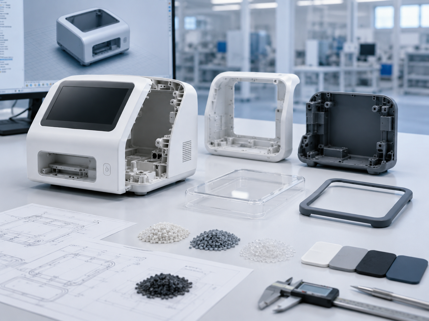
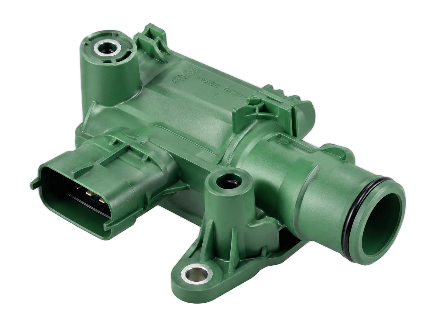
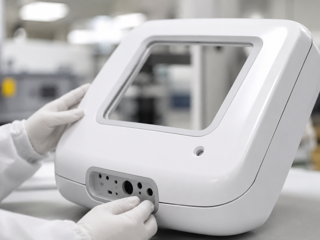
The product was a compact diagnostic device with a white PC/ABS housing, front cosmetic cover, display window, reagent card interface opening, internal PCB supports, multiple screw bosses, and snap-fits on the upper cover. The pilot quantity was around 500 sets, with possible annual demand of 3,000–5,000 sets after validation.
The customer had already tested 3D printed prototypes. The prototype assembly was acceptable, but the customer needed real molded parts to validate cosmetic quality, shrinkage, warpage, assembly fit, interface alignment, and critical dimensions.
During DFM review, several risks were identified:
- screw bosses and ribs were located behind cosmetic surfaces;
- the upper cover had a large surface area with uneven internal reinforcement;
- some snap-fits created undercut risk;
- the reagent card interface required stable tolerance control;
- the white enclosure was sensitive to dust, fingerprints, and surface marks;
- annual demand was not yet stable enough for full production tooling.
The project did not move directly into full production tooling.
A more practical route was selected:
DFM optimization → shared mold base rapid tooling → trial molding → high-cleanliness molding and handling support → pilot production
Before tooling, the screw boss roots were reduced, supporting ribs were adjusted, rib thickness behind cosmetic surfaces was controlled, snap-fit direction was reviewed to reduce slider risk, wall thickness around the reagent card opening was improved, and cosmetic A-surfaces were defined.
After confirming that the part size and mold structure were suitable, shared mold base rapid tooling was selected. This allowed the customer to obtain real molded parts faster while avoiding premature investment in full production tooling.
Because the product was a white diagnostic device housing, high-cleanliness molding and handling support was also applied. The control plan included cleaner molding conditions, controlled handling, glove handling for cosmetic surfaces where needed, separated packaging, A-surface inspection, and dust/fingerprint control during packaging.
The project achieved four practical goals:
- The customer obtained real molded parts instead of relying only on 3D printed prototypes.
- Early tooling investment was controlled through shared mold base rapid tooling.
- Cleaner molding and handling improved control of white cosmetic surfaces.
- Pilot production issues could be identified before larger-volume production.
This example shows that the best manufacturing path for a low-volume diagnostic device enclosure is not always the cheapest prototype process or the most complete production mold. The better path is the one that fits the current engineering stage.
10. How Rapid MFG Online Supports Medical Device Enclosure Projects
Rapid MFG Online is most useful when customers need more than a manufacturing quote.
Many customers already have industrial design, CAD files, early prototypes, and a planned validation quantity. What they need is a practical path to real molded parts and low-volume production.
Rapid MFG Online can support these projects through:
- CAD and drawing review;
- pre-tooling DFM risk identification;
- material and manufacturing process review;
- process selection among 3D printing, CNC machining, vacuum casting, rapid tooling, and injection molding;
- shared mold base rapid tooling when suitable;
- trial molding and molded part validation;
- high-cleanliness molding and handling support;
- low-volume production coordination;
- cosmetic inspection, packaging, and delivery control.
The goal is not just to manufacture a plastic enclosure.
The goal is to reduce design risk, tooling risk, molding risk, cosmetic risk, assembly risk, cleanliness risk, and low-volume production risk before they become expensive problems.
Conclusion
Medical device enclosure manufacturing should not be approached as ordinary plastic part purchasing.
For diagnostic equipment, medical instruments, POCT devices, laboratory equipment, and low-volume medical products, key risks usually appear before production begins. Wall thickness may not be suitable for molding. Internal ribs and screw bosses may affect cosmetic surfaces. Snap-fits may increase tooling complexity. Assembly tolerances may not remain stable after molding. Prototypes may not represent real molded parts. Early volume may not justify full production tooling. Cleanliness and packaging requirements may not be clearly defined.
Shared mold base rapid tooling helps suitable projects obtain real molded parts faster while controlling early tooling investment.
High-cleanliness molding and handling support helps control dust, fingerprints, surface marks, and handling contamination for medical and diagnostic equipment enclosures.
The final goal is not just to make an enclosure. It is to help engineering teams move from design validation to low-volume production with lower manufacturing risk.
If you are developing a medical device enclosure, diagnostic equipment housing, or low-volume plastic component, a DFM review before tooling can help reduce mold risk, molding issues, cosmetic defects, assembly problems, and production delays.
Send us your CAD files, expected quantity, material requirements, cosmetic surface requirements, assembly requirements, and any cleanliness or packaging requirements. We can help review your enclosure design and recommend a suitable manufacturing path, including prototype manufacturing, CNC machining, vacuum casting, rapid tooling, shared mold base tooling when suitable, low-volume injection molding, or production tooling when appropriate.